This is the third article in the Oil Analysis 101 series and focuses on detecting and monitoring water content. While there are typically only one or two methods commonly used for measuring most oil properties, there are many methods that can be used for detecting the water-in-oil concentrations. Each method is important because it can be effective in different situations. In this article, we will discuss which methods are available for determining the moisture content of a used oil sample and discuss their strengths, weaknesses and limitations.
Water is perhaps the most harmful of all contaminants with the exception of solid particles. While the presence of water is often overlooked as the primary root cause of machine problems, excess moisture contamination can lead to premature oil degradation, increased corrosion and increased wear.
Visual Crackle Test
The simplest way to determine the presence of water in oil is to use the Visual Crackle test. While this is an effective test for identifying free and emulsified water down to say 500 ppm, its biggest limitation is that the test is nonquantitative and fairly subjective. False positives are possible with entrained volatile solvents and gases. Nevertheless, as a screening tool in the lab and the field, the crackle test will always have a role to play where a quick yes or no answer is required for free and emulsified water.
FTIR Analysis
FTIR can be an effective method for screening samples containing in excess of 1,000 ppm of water, provided a correct new oil baseline is available for spectral subtraction. However, due to its limited precision and comparatively high detection limits, FTIR is not adequate in many situations where precise water concentrations below 1,000 ppm or 0.1 percent are required.
Dean and Stark Method
The classic method for determining water-in-oil is the Dean and Stark distillation method (ASTM D95). This test method is fairly cumbersome and requires a comparatively large sample to ensure accuracy, which is why it is rarely used in production-style oil analysis labs today. The method involves the direct codistillation of the oil sample. As the oil is heated, any water present vaporizes. The water vapors are then condensed and collected in a graduated collection tube, such that the volume of water produced by distillation can be measured as a function of the total volume of oil used.
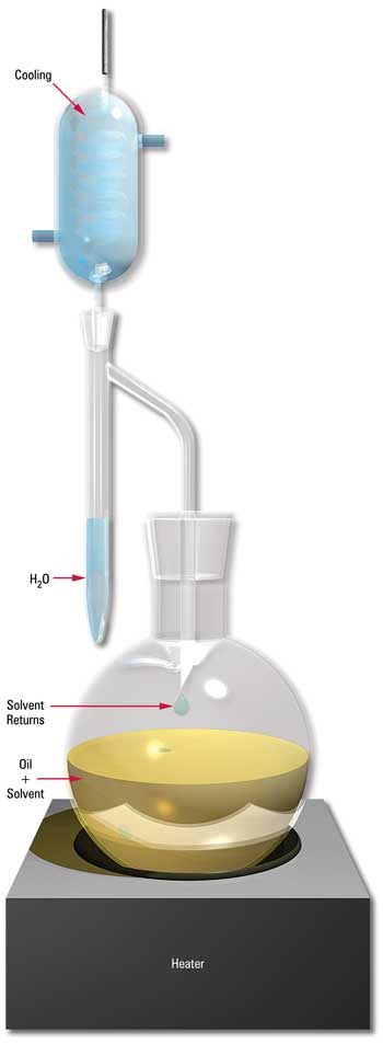 |
Dean and Stark Distillation Apparatus (ASTM D95) |
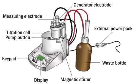
Karl Fischer Moisture
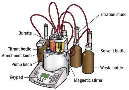
The Karl Fischer Moisture test is the method of choice when accuracy and precision are required in determining the amount of free, dissolved and emulsified water in an oil sample. However, even within the scope of Karl Fischer testing, there are several methodologies that are used.
All Karl Fischer procedures work in essentially the same way. The oil sample is titrated with a standard Karl Fischer reagent until an end-point is reached. The difference in test methods is based on the amount of sample used for the test and the method used to determine the titration end-point.
The most frequently used Karl Fischer method follows ASTM D1744 and involves volumetric titration of the sample, using a potentiometric cell to determine the end-point. While this method is reliable and precise, there can be reproducibility problems at low water concentrations (200 ppm or less). In addition, the test can be subject to interferences from sulfurous additives (for instance, AW and EP-type additives) and ferric salts which may be present due to wear debris. Both of these react with the Karl Fischer reagent as if they were water and can give a false positive, resulting in an overstating of the water concentration. In fact, a new, clean, dry AW or EP oil may give a reading of as much as 200 to 300 ppm, due to the reaction of the additives, rather than because of excess moisture.
More recently, labs have been switching to a coulometric titration method described in ASTM D6304. This method is more reliable than D1744 at low water concentrations and is less prone to interference effects, although again, AW and EP additized oils can show as much as 100 ppm of water as a result of the effects of the sulfurous additives.
The most reliable method is ASTM D6304, complete with codistillation. With the codistillation method, the oil sample is heated under a vacuum so that any water present in the sample evaporates. The water vapors are condensed and dissolved into toluene, which is then titrated using the D6304 procedure. Because the additives and other interfering contaminants that may be present in a used oil sample remain dissolved or suspended in the oil, the condensed water in the toluene is free from interference effects and is a true count of water present in the sample.
Another less commonly used method is ASTM D1533, which is used for determining water concentrations down to 10 ppm or less in transformer oils using a coulometric Karl Fischer reagent.
Calcium Hydride Test Kits
One of the simplest and most convenient ways to determine water concentrations in the field is by using a calcium hydride test kit. This method employs the known reaction of water with solid calcium hydride to produce hydrogen gas. Because the reaction occurs stoiciometrically, the amount of hydrogen gas liberated is directly proportional to the amount of water present in the sample. Therefore, the water content of the sample can be determined by measuring the rise in pressure in a sealed container due to the liberation of hydrogen gas as any water in the sample reacts with the calcium hydride. Used correctly, these test kits are reported to be accurate down to 50 ppm free or emulsified water.
Saturation Meters
When the amount of water present in an oil sample is below the saturation point, saturation (dew-point) meters can be used to indirectly quantify water content. The saturation point of an oil is simply the point at which the oil contains as much water in the dissolved state as possible, at a given temperature. At this point, the oil is saturated or has a relative humidity of 100 percent. Most saturation meters use a thin film capacitive device, whose capacitance changes depending on the relative humidity of the fluid in which it is submerged. Saturation meters have proven to be accurate and reliable at determining the percent saturation of used oils.
The biggest drawback with saturation meters is the fact that the saturation point is strongly dependent on temperature as well as the presence (or absence) of polar species, including additives, contaminants and wear particles. In addition, with water levels in excess of the saturation point, typically 200 to 600 ppm for most industrial oils, saturation meters are unable to quantify water content accurately. Despite these limitations, saturation meters can be a useful trending tool to determine moisture onsite, provided they are used frequently and routinely.
Monitoring and controlling water levels in any lubricating system is important. Whether it is a large diesel engine, a steam turbine, a hydraulic system or an electrical transformer, water can have a significant impact on equipment reliability and longevity. Regular water monitoring, whether it be a simple onsite crackle test or a lab-based Karl Fischer moisture test should become a standard condition-monitoring tool. But remember, like all tests, the methods used to detect water in oil have strengths and weakness, so be sure to select the one that meets your needs and desired detection limits.


 Water
contamination in lubricating oil accelerates the natural oxidation that normally
takes place in the oil. Even when additives are used to retard the natural process,
the presence of water will degrade the effectiveness of certain additives potentially
leading to tight emulsions and the formation of sediment in the oil. In addition,
water in lubricating oil increases the risk of microbial attack and contributes
to further loss of oil performance and thereby to corrosion of the components
in the various oil systems.
Water
contamination in lubricating oil accelerates the natural oxidation that normally
takes place in the oil. Even when additives are used to retard the natural process,
the presence of water will degrade the effectiveness of certain additives potentially
leading to tight emulsions and the formation of sediment in the oil. In addition,
water in lubricating oil increases the risk of microbial attack and contributes
to further loss of oil performance and thereby to corrosion of the components
in the various oil systems.